Two examples that actually look like very similar circuits can be found in these detail images. (Click the detail image to get PyroSama's original.)
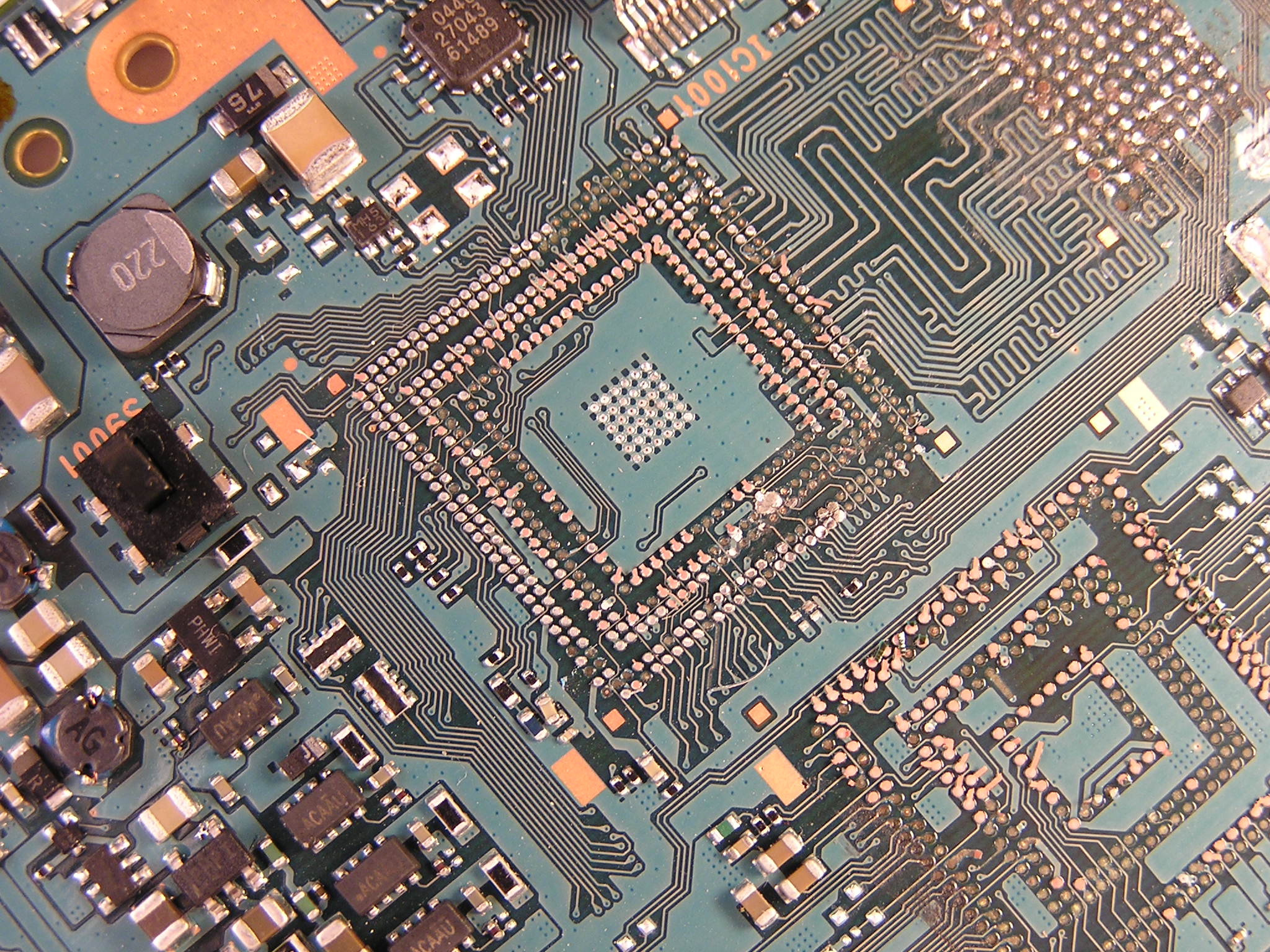
Just north of the main CPU, this circuit appears to be able to connect to the circuit that runs the IrDA port, if it were populated with the right components. Especially interesting because of the four large test points in the middle of this area:
Likewise, on the SIRCS/Wifi/Memory Stick daughterboard, there is another circuit that looks very similar:
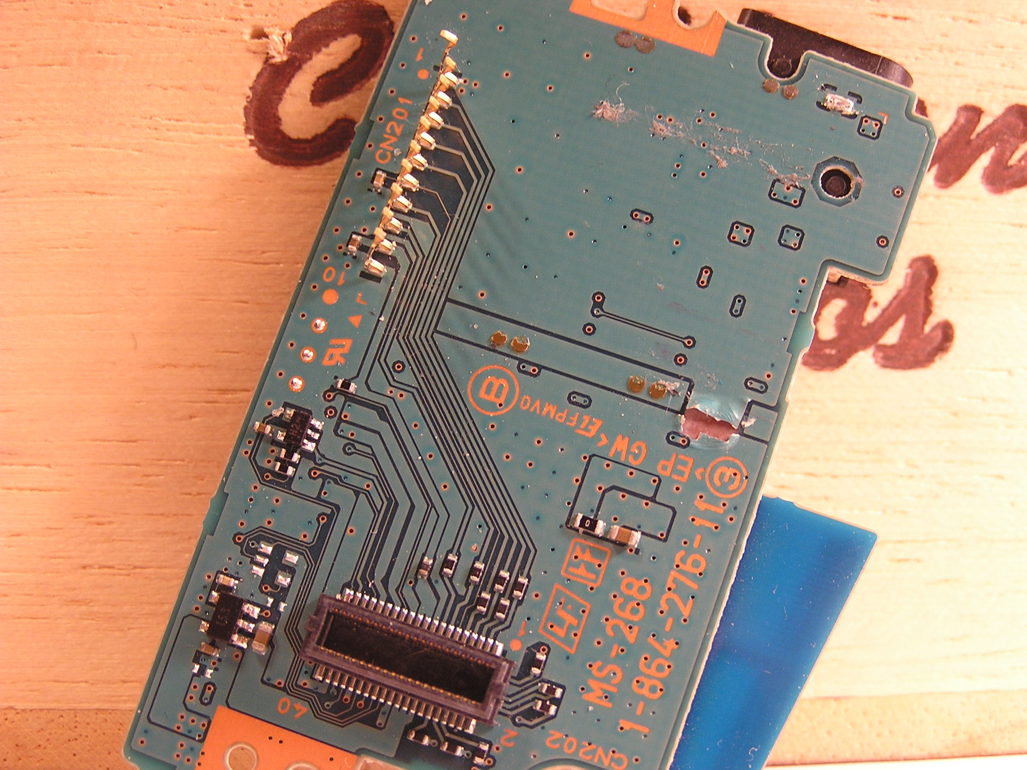
I haven't yet figured out what the 5-terminal devices are, but they look like they could be voltage regulators.
It is rumored that developers can load test code right onto the PSP through the SIRCS connector beside the headphone jack. It might make sense that a retail PSP would lack the physical hardware to make this possible. I want to trace these circuits out to see whether they show any promise. It might be possible to populate these circuits by hand (yes, I know some very good technicians!) and activate features that are not meant to be available to retail customers.
There are a few other places on the boards that have stuff like this going on as well.
Thanks again for the pictures, PyroSama! I always manage to notice something new every time I look at these that I have overlooked when studying the actual boards!
EDIT:
I might have gotten a bit circle-happy with that second image - the circle in the lower left actually is populated.
Not much info to go by on looking up those 5-terminal devices, but another possibility is that they are op-amps.
